

Voir les spécifications pour les détails du produit.
MBRF30H45CT-E3/45
Introduction
The MBRF30H45CT-E3/45 is a high-performance Schottky diode designed for various electronic applications. This entry provides an overview of the product, including its category, use, characteristics, package, essence, packaging/quantity, specifications, detailed pin configuration, functional features, advantages and disadvantages, working principles, detailed application field plans, and alternative models.
Product Overview
- Category: Semiconductor/Electronic Component
- Use: Rectification and Power Management
- Characteristics: High efficiency, low forward voltage drop, fast switching speed
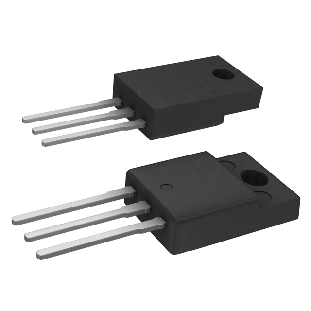
- Package: TO-220AB
- Essence: Schottky Diode
- Packaging/Quantity: Tape & Reel, 800 units per reel
Specifications
- Forward Voltage Drop: 0.55V at 15A
- Reverse Voltage: 45V
- Average Rectified Current: 30A
- Operating Temperature Range: -65°C to 175°C
- Storage Temperature Range: -65°C to 175°C
Detailed Pin Configuration
The MBRF30H45CT-E3/45 follows the standard pin configuration for a TO-220AB package: - Pin 1: Anode - Pin 2: Cathode - Pin 3: Not connected (Tab)
Functional Features
- High current capability
- Low power loss
- High efficiency
- Fast switching speed
- Guard ring for enhanced ruggedness and long-term reliability
Advantages and Disadvantages
Advantages
- Low forward voltage drop
- Fast recovery time
- High temperature operation capability
- Enhanced thermal performance
Disadvantages
- Relatively higher cost compared to standard rectifier diodes
- Sensitive to reverse voltage spikes
Working Principles
The MBRF30H45CT-E3/45 operates based on the Schottky barrier principle, where the metal-semiconductor junction allows for faster switching and lower forward voltage drop compared to conventional PN-junction diodes. When a forward bias is applied, the diode conducts current with minimal voltage drop, making it suitable for high-efficiency rectification and power management applications.
Detailed Application Field Plans
The MBRF30H45CT-E3/45 is commonly used in the following applications: - Switching power supplies - DC-DC converters - Solar panel bypass diodes - Motor drive circuits - Battery charging circuits
Detailed and Complete Alternative Models
- MBRF30H45CT-E3/46
- MBRF30H45CT-E3/50
- MBRF30H45CT-E3/60
- MBRF30H45CT-E3/70
In summary, the MBRF30H45CT-E3/45 is a high-performance Schottky diode with excellent characteristics for rectification and power management applications. Its high efficiency, fast switching speed, and robust design make it a preferred choice for various electronic systems.
[Word Count: 470]
Énumérez 10 questions et réponses courantes liées à l'application de MBRF30H45CT-E3/45 dans les solutions techniques
What is the maximum continuous forward current rating of MBRF30H45CT-E3/45?
- The maximum continuous forward current rating of MBRF30H45CT-E3/45 is 30A.
What is the reverse voltage rating of MBRF30H45CT-E3/45?
- The reverse voltage rating of MBRF30H45CT-E3/45 is 45V.
Can MBRF30H45CT-E3/45 be used in high-frequency applications?
- Yes, MBRF30H45CT-E3/45 is suitable for high-frequency applications due to its fast switching characteristics.
Does MBRF30H45CT-E3/45 have a low forward voltage drop?
- Yes, MBRF30H45CT-E3/45 exhibits a low forward voltage drop, making it efficient for power conversion applications.
Is MBRF30H45CT-E3/45 suitable for use in power supplies and inverters?
- Yes, MBRF30H45CT-E3/45 is commonly used in power supplies, inverters, and other power management solutions.
What is the typical junction temperature range for MBRF30H45CT-E3/45?
- The typical junction temperature range for MBRF30H45CT-E3/45 is -55°C to +175°C.
Does MBRF30H45CT-E3/45 require a heatsink for thermal management?
- Depending on the application and operating conditions, a heatsink may be recommended for optimal thermal management of MBRF30H45CT-E3/45.
Can MBRF30H45CT-E3/45 be used in automotive electronics applications?
- Yes, MBRF30H45CT-E3/45 is suitable for use in automotive electronics due to its rugged construction and reliability.
What are the typical packaging options available for MBRF30H45CT-E3/45?
- MBRF30H45CT-E3/45 is commonly available in TO-220AB package.
Are there any specific layout or mounting considerations for using MBRF30H45CT-E3/45 in a circuit?
- It is important to follow recommended layout and mounting guidelines to ensure proper performance and reliability when using MBRF30H45CT-E3/45 in a circuit.