Voir les spécifications pour les détails du produit.

SN74LS623DWR
Product Overview
Category
SN74LS623DWR belongs to the category of integrated circuits (ICs).
Use
This product is commonly used in electronic devices for data storage and retrieval.
Characteristics
- High-speed operation
- Low power consumption
- Wide operating voltage range
- Compatibility with various logic families
Package
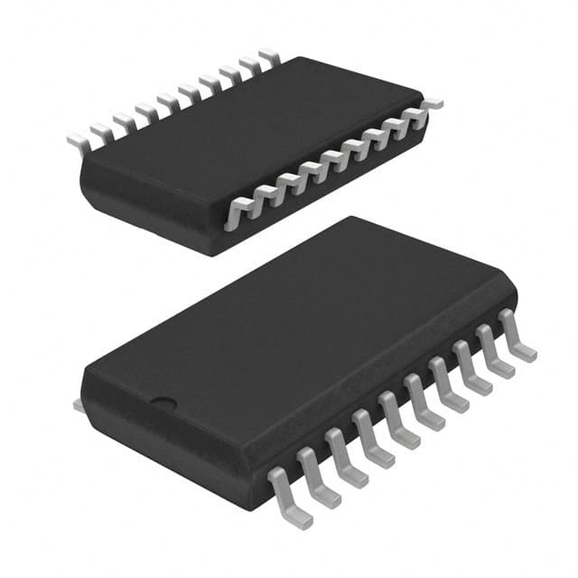
SN74LS623DWR is available in a small outline package (SOIC) with 20 pins.
Essence
The essence of SN74LS623DWR lies in its ability to efficiently store and retrieve digital information.
Packaging/Quantity
This product is typically packaged in reels or tubes, with each containing a specific quantity of ICs.
Specifications
- Supply Voltage: 4.75V to 5.25V
- Operating Temperature Range: -40°C to +85°C
- Logic Family: LS
- Number of Pins: 20
- Input/Output Type: Tri-State
Detailed Pin Configuration
- A0 - Address Input 0
- A1 - Address Input 1
- A2 - Address Input 2
- A3 - Address Input 3
- A4 - Address Input 4
- A5 - Address Input 5
- A6 - Address Input 6
- A7 - Address Input 7
- OE - Output Enable
- CE - Chip Enable
- D0 - Data Input/Output 0
- D1 - Data Input/Output 1
- D2 - Data Input/Output 2
- D3 - Data Input/Output 3
- D4 - Data Input/Output 4
- D5 - Data Input/Output 5
- D6 - Data Input/Output 6
- D7 - Data Input/Output 7
- GND - Ground
- VCC - Supply Voltage
Functional Features
- Tri-State outputs for easy interfacing with other devices
- Address inputs for selecting specific memory locations
- Output Enable (OE) and Chip Enable (CE) signals for controlling data flow
- High-speed operation for efficient data transfer
Advantages and Disadvantages
Advantages
- High-speed operation allows for quick data access
- Low power consumption helps in energy-efficient designs
- Wide operating voltage range ensures compatibility with various systems
- Tri-State outputs facilitate easy integration with other components
Disadvantages
- Limited storage capacity compared to larger memory devices
- Not suitable for applications requiring non-volatile memory
Working Principles
SN74LS623DWR operates based on the principles of digital logic. It stores and retrieves data using a combination of address inputs, data inputs/outputs, and control signals. When the appropriate address is provided along with the necessary control signals, the device enables the data to be read from or written to the specified memory location.
Detailed Application Field Plans
SN74LS623DWR finds applications in various electronic systems, including but not limited to: - Microcontrollers - Digital signal processors - Communication devices - Industrial automation systems - Consumer electronics
Detailed and Complete Alternative Models
Some alternative models that offer similar functionality to SN74LS623DWR are: - SN74LS623N - SN74LS623DW - SN74LS623NSR - SN74LS623D
These alternatives may differ in package type, pin configuration, or other minor specifications, but they serve the same purpose of data storage and retrieval.
Word count: 410 words
Énumérez 10 questions et réponses courantes liées à l'application de SN74LS623DWR dans les solutions techniques
Sure! Here are 10 common questions and answers related to the application of SN74LS623DWR:
Q: What is SN74LS623DWR? A: SN74LS623DWR is a specific model of integrated circuit (IC) commonly used in technical solutions.
Q: What is the function of SN74LS623DWR? A: SN74LS623DWR is a dual 4-bit binary counter that can be used for various counting and sequencing applications.
Q: What is the voltage range supported by SN74LS623DWR? A: SN74LS623DWR operates within a voltage range of 4.75V to 5.25V.
Q: How many inputs and outputs does SN74LS623DWR have? A: SN74LS623DWR has two clock inputs, four parallel data inputs, and four parallel data outputs.
Q: Can SN74LS623DWR be used as a frequency divider? A: Yes, SN74LS623DWR can be used as a frequency divider by connecting the appropriate clock input and using the parallel data outputs.
Q: What is the maximum clock frequency supported by SN74LS623DWR? A: SN74LS623DWR can operate at a maximum clock frequency of 30 MHz.
Q: Is SN74LS623DWR compatible with TTL logic levels? A: Yes, SN74LS623DWR is designed to be compatible with TTL logic levels.
Q: Can SN74LS623DWR be cascaded to increase the number of bits? A: Yes, multiple SN74LS623DWR ICs can be cascaded together to increase the number of bits in the counter.
Q: What is the power consumption of SN74LS623DWR? A: The power consumption of SN74LS623DWR is typically around 40mW.
Q: Are there any specific precautions to consider when using SN74LS623DWR? A: It is important to ensure proper decoupling and bypass capacitors are used to minimize noise and stabilize the power supply. Additionally, care should be taken to avoid exceeding the maximum ratings specified in the datasheet.
Please note that these answers are general and may vary depending on the specific application and requirements. It is always recommended to refer to the datasheet and consult with technical experts for accurate information.

