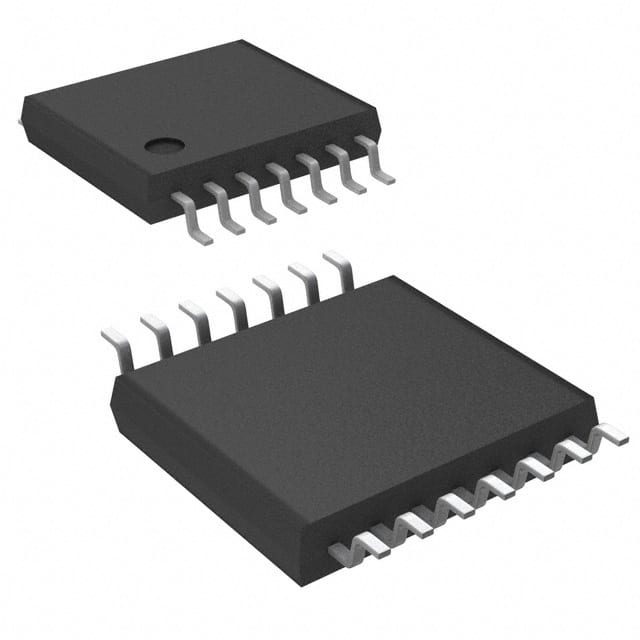
Voir les spécifications pour les détails du produit.

SN74CBT3125CPWRE4
Product Overview
- Category: Integrated Circuit (IC)
- Use: Digital Multiplexer/Demultiplexer
- Characteristics: High-speed, low-power consumption
- Package: TSSOP (Thin Shrink Small Outline Package)
- Essence: 4-bit multiplexer/demultiplexer
- Packaging/Quantity: Tape and Reel, 2500 units per reel
Specifications
- Supply Voltage Range: 2 V to 6 V
- Input Voltage Range: 0 V to VCC
- Output Voltage Range: 0 V to VCC
- On-State Resistance: 5 Ω (typical)
- Bandwidth: 400 MHz (typical)
- Operating Temperature Range: -40°C to +85°C
Detailed Pin Configuration
The SN74CBT3125CPWRE4 has a total of 16 pins. The pin configuration is as follows:
- A1 - Select Input 1
- B1 - Data Input/Output 1
- OE - Output Enable Input
- Y1 - Data Output 1
- GND - Ground
- Y2 - Data Output 2
- B2 - Data Input/Output 2
- A2 - Select Input 2
- VCC - Power Supply
- A3 - Select Input 3
- B3 - Data Input/Output 3
- Y3 - Data Output 3
- A4 - Select Input 4
- B4 - Data Input/Output 4
- Y4 - Data Output 4
- GND - Ground
Functional Features
- 4-bit multiplexer/demultiplexer with independent control inputs
- Low power consumption
- High-speed operation
- Wide operating voltage range
- Break-before-make switching action for non-overlapping control inputs
Advantages and Disadvantages
Advantages: - Versatile multiplexer/demultiplexer functionality - Low power consumption - High-speed operation - Wide operating voltage range allows for compatibility with various systems
Disadvantages: - Limited number of input/output channels (4-bit)
Working Principles
The SN74CBT3125CPWRE4 is a digital multiplexer/demultiplexer IC that allows for the selection of one of four data inputs to be routed to a single output line. The selection is controlled by the input signals applied to the select inputs (A1, A2, A3, A4). The output enable input (OE) enables or disables the outputs.
When the appropriate select inputs are activated, the corresponding data input is connected to the output line. The IC operates on a break-before-make principle, ensuring that there is no overlap between the switching of inputs.
Detailed Application Field Plans
The SN74CBT3125CPWRE4 can be used in various applications, including:
- Data communication systems: Multiplexing and demultiplexing of digital signals in communication networks.
- Digital audio/video systems: Switching between different audio/video sources.
- Test and measurement equipment: Selecting different test signals for analysis.
- Industrial automation: Routing control signals in automated systems.
- Automotive electronics: Signal routing in automotive control modules.
Detailed and Complete Alternative Models
Some alternative models to the SN74CBT3125CPWRE4 include:
- CD4051B: 8-channel analog multiplexer/demultiplexer IC.
- 74HC151: 8-input multiplexer IC.
- SN74LVC1G3157: Single-pole double-throw (SPDT) analog switch IC.
These alternative models offer different features and specifications, providing flexibility for various application requirements.
Word count: 408 words
Énumérez 10 questions et réponses courantes liées à l'application de SN74CBT3125CPWRE4 dans les solutions techniques
Sure! Here are 10 common questions and answers related to the application of SN74CBT3125CPWRE4 in technical solutions:
Q: What is SN74CBT3125CPWRE4? A: SN74CBT3125CPWRE4 is a quad bus switch IC (Integrated Circuit) that allows multiple input/output signals to be connected or disconnected in electronic circuits.
Q: What is the purpose of using SN74CBT3125CPWRE4 in technical solutions? A: SN74CBT3125CPWRE4 is commonly used to enable or disable communication between different components or subsystems in electronic systems, such as multiplexing/demultiplexing signals or connecting/disconnecting peripheral devices.
Q: What voltage levels does SN74CBT3125CPWRE4 support? A: SN74CBT3125CPWRE4 supports voltage levels ranging from 1.65V to 5.5V, making it compatible with a wide range of digital logic families.
Q: How many channels does SN74CBT3125CPWRE4 have? A: SN74CBT3125CPWRE4 has four independent bidirectional channels, allowing it to handle up to four separate signal paths simultaneously.
Q: Can SN74CBT3125CPWRE4 handle high-speed signals? A: Yes, SN74CBT3125CPWRE4 is designed to support high-speed data rates, making it suitable for applications requiring fast switching and low propagation delay.
Q: Does SN74CBT3125CPWRE4 have built-in ESD protection? A: Yes, SN74CBT3125CPWRE4 incorporates built-in ESD (Electrostatic Discharge) protection, which helps safeguard the IC from damage caused by static electricity.
Q: Can SN74CBT3125CPWRE4 be used in both analog and digital circuits? A: Yes, SN74CBT3125CPWRE4 can be used in both analog and digital circuits, as it supports bidirectional signal transmission and has low ON-state resistance.
Q: What is the maximum current that SN74CBT3125CPWRE4 can handle? A: SN74CBT3125CPWRE4 has a maximum continuous current rating of 128mA per channel, making it suitable for most low to moderate current applications.
Q: Does SN74CBT3125CPWRE4 require external pull-up or pull-down resistors? A: No, SN74CBT3125CPWRE4 has built-in weak pull-up and pull-down resistors, eliminating the need for external resistors in most cases.
Q: Are there any specific layout considerations when using SN74CBT3125CPWRE4? A: Yes, it is recommended to follow the manufacturer's guidelines for proper PCB layout, including minimizing trace lengths, reducing noise coupling, and providing adequate decoupling capacitors near the IC.
Please note that these answers are general and may vary depending on the specific application and requirements. It is always advisable to refer to the datasheet and consult with the manufacturer for detailed information.

