

Voir les spécifications pour les détails du produit.
SN74ALVTH16827GR
Product Overview
- Category: Integrated Circuit (IC)
- Use: Logic Level Translator
- Characteristics: High-speed, low-voltage, 20-bit bus transceiver
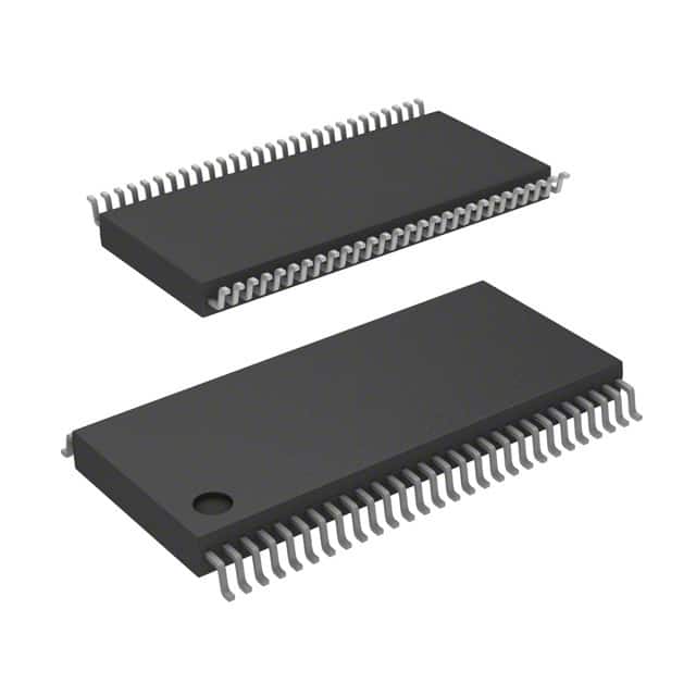
- Package: TSSOP (Thin Shrink Small Outline Package)
- Essence: Translates signals between different voltage levels in digital systems
- Packaging/Quantity: Tape and Reel, 2500 units per reel
Specifications
- Supply Voltage Range: 1.2V to 3.6V
- Input Voltage Range: 0V to VCC
- Output Voltage Range: 0V to VCC
- Operating Temperature Range: -40°C to +85°C
- Propagation Delay Time: 2.5ns (Max)
- Output Current: ±24mA
- ESD Protection: >2000V
Detailed Pin Configuration
The SN74ALVTH16827GR has a total of 56 pins, which are divided into various groups:
- Group A (pins 1-14): Data Inputs/Outputs (D0-D13)
- Group B (pins 15-28): Voltage Translation Control Inputs (DIR, OE, GND, VCC)
- Group C (pins 29-42): Voltage Translation Control Outputs (DIR, OE, GND, VCC)
- Group D (pins 43-56): Power Supply and Ground Pins (VCC, GND)
Functional Features
- Bidirectional voltage translation between two independent buses
- Supports mixed-mode signal operation on each port
- Provides non-inverting level shifting
- Allows voltage level translation from 1.2V to 3.6V
Advantages and Disadvantages
Advantages: - High-speed operation - Low-voltage operation - Wide supply voltage range - ESD protection for robustness - Bidirectional data flow
Disadvantages: - Limited number of bits (20-bit bus transceiver) - Requires external control signals for voltage translation
Working Principles
The SN74ALVTH16827GR operates by receiving input signals from one bus and translating them to the voltage level of another bus. It uses a combination of level shifting circuits and bidirectional buffers to achieve this voltage translation. The direction of translation is controlled by the DIR pin, while the OE pin enables or disables the output buffers.
Detailed Application Field Plans
The SN74ALVTH16827GR is commonly used in various applications where voltage translation between different logic levels is required. Some specific application fields include:
- Microcontrollers and microprocessors
- Communication systems
- Data acquisition systems
- Industrial automation
- Automotive electronics
Detailed and Complete Alternative Models
- SN74LVC1T45: Single-Bit Dual-Supply Bus Transceiver
- SN74AVC4T245: 4-Bit Dual-Supply Bus Transceiver
- SN74LVCH16244A: 16-Bit Bus Transceiver with 3-State Outputs
- SN74LVC8T245: 8-Bit Dual-Supply Bus Transceiver
- SN74AVC16T245: 16-Bit Dual-Supply Bus Transceiver
These alternative models offer similar functionality and can be considered as alternatives to the SN74ALVTH16827GR based on specific requirements and system constraints.
In conclusion, the SN74ALVTH16827GR is a high-speed, low-voltage logic level translator IC that facilitates voltage translation between different digital systems. With its wide supply voltage range and bidirectional data flow capability, it finds applications in various fields such as microcontrollers, communication systems, and industrial automation.
Énumérez 10 questions et réponses courantes liées à l'application de SN74ALVTH16827GR dans les solutions techniques
Sure! Here are 10 common questions and answers related to the application of SN74ALVTH16827GR:
Q: What is SN74ALVTH16827GR? A: SN74ALVTH16827GR is a 20-bit buffer/driver with 3-state outputs, designed for low-voltage (1.65V to 3.6V) applications.
Q: What is the maximum operating frequency of SN74ALVTH16827GR? A: The maximum operating frequency of SN74ALVTH16827GR is typically around 400 MHz.
Q: Can SN74ALVTH16827GR be used in both input and output applications? A: Yes, SN74ALVTH16827GR can be used as both an input buffer and an output driver.
Q: What is the purpose of the 3-state outputs in SN74ALVTH16827GR? A: The 3-state outputs allow multiple devices to share a common bus without interfering with each other.
Q: What is the power supply voltage range for SN74ALVTH16827GR? A: SN74ALVTH16827GR operates within a power supply voltage range of 1.65V to 3.6V.
Q: Can SN74ALVTH16827GR tolerate overvoltage on its inputs? A: No, SN74ALVTH16827GR is not designed to tolerate overvoltage on its inputs. It is recommended to stay within the specified voltage range.
Q: Does SN74ALVTH16827GR have built-in ESD protection? A: Yes, SN74ALVTH16827GR has built-in ESD protection, which helps protect the device from electrostatic discharge.
Q: What is the output drive strength of SN74ALVTH16827GR? A: The output drive strength of SN74ALVTH16827GR is typically around 12 mA.
Q: Can SN74ALVTH16827GR be used in automotive applications? A: Yes, SN74ALVTH16827GR is qualified for automotive applications and meets the necessary standards.
Q: Are there any specific layout considerations for using SN74ALVTH16827GR? A: Yes, it is recommended to follow the layout guidelines provided in the datasheet to ensure proper performance and minimize signal integrity issues.
Please note that these answers are general and may vary depending on the specific application and requirements. It is always recommended to refer to the datasheet and consult with the manufacturer for detailed information.