

Voir les spécifications pour les détails du produit.
SN74AC74NSR
Product Overview
- Category: Integrated Circuit (IC)
- Use: Flip-Flop
- Characteristics: Dual D-Type Positive-Edge-Triggered Flip-Flop
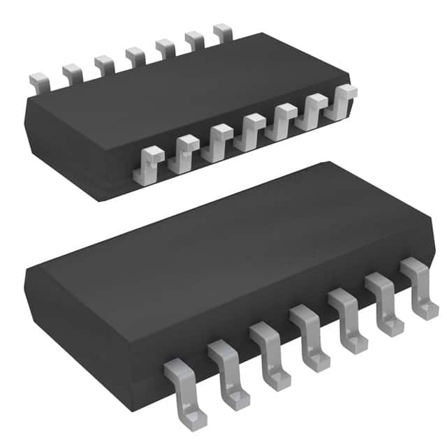
- Package: 14-SOIC (Small Outline Integrated Circuit)
- Essence: This IC is a dual flip-flop that can store and transfer data in electronic circuits.
- Packaging/Quantity: Available in reels of 2500 pieces.
Specifications
- Supply Voltage Range: 2V to 6V
- High-Level Input Voltage: 2V to VCC
- Low-Level Input Voltage: GND to 0.8V
- High-Level Output Current: -24mA
- Low-Level Output Current: 24mA
- Operating Temperature Range: -40°C to 85°C
Detailed Pin Configuration
The SN74AC74NSR has a total of 14 pins, which are labeled as follows:
- CLR (Clear) - Clear input pin
- D1 (Data 1) - Data input for the first flip-flop
- CLK (Clock) - Clock input pin
- D2 (Data 2) - Data input for the second flip-flop
- Q1 (Output 1) - Output of the first flip-flop
- Q1' (Complementary Output 1) - Complementary output of the first flip-flop
- GND (Ground) - Ground reference pin
- Q2' (Complementary Output 2) - Complementary output of the second flip-flop
- Q2 (Output 2) - Output of the second flip-flop
- PRE (Preset) - Preset input pin
- PR' (Complementary Preset) - Complementary preset input pin
- CLR' (Complementary Clear) - Complementary clear input pin
- VCC (Supply Voltage) - Positive supply voltage pin
- PR (Preset) - Preset input pin
Functional Features
- Dual flip-flop with independent data inputs and outputs.
- Positive-edge-triggered operation allows for synchronized data transfer.
- Clear and preset inputs provide control over the flip-flop state.
- Complementary outputs provide both normal and inverted versions of the stored data.
Advantages and Disadvantages
Advantages: - Dual flip-flop design allows for efficient storage and transfer of two separate data signals. - Positive-edge-triggered operation ensures reliable synchronization. - Clear and preset inputs offer flexibility in controlling the flip-flop state.
Disadvantages: - Limited to positive-edge triggering, may not be suitable for applications requiring negative-edge triggering. - Only supports D-type flip-flop functionality, not suitable for other types of flip-flops.
Working Principles
The SN74AC74NSR operates based on the principles of positive-edge-triggered flip-flops. When a rising edge is detected on the clock input (CLK), the data present at the D1 and D2 inputs is transferred to the Q1 and Q2 outputs, respectively. The clear (CLR) and preset (PRE) inputs allow for resetting or setting the flip-flop outputs to specific states. The complementary outputs (Q1', Q2') provide inverted versions of the stored data.
Detailed Application Field Plans
The SN74AC74NSR can be used in various applications that require the storage and transfer of digital data. Some potential application fields include:
- Digital Communication Systems: Used for data buffering and synchronization in communication protocols.
- Microcontrollers and Processors: Employed for register storage and data transfer within the system.
- Data Storage Systems: Integrated into memory modules and storage devices for data handling.
- Control Systems: Utilized for state storage and synchronization in control circuits.
Detailed and Complete Alternative Models
- SN74AC74D - Dual D-Type Positive-Edge-Triggered Flip-Flop in 14-SOIC package.
- MC74AC74N - Dual D-Type Positive-Edge-Triggered Flip-Flop in 14-DIP (Dual In-Line Package).
- CD74AC74E - Dual D-Type Positive-Edge-Triggered Flip-Flop in 14-PDIP (Plastic Dual In-Line Package).
These alternative models offer similar functionality and characteristics to the SN74AC74NSR, providing options for different packaging preferences or availability.
Word count: 511 words
Énumérez 10 questions et réponses courantes liées à l'application de SN74AC74NSR dans les solutions techniques
Sure! Here are 10 common questions and answers related to the application of SN74AC74NSR in technical solutions:
Q: What is SN74AC74NSR? A: SN74AC74NSR is a dual D-type flip-flop integrated circuit (IC) that can store one bit of data.
Q: What is the voltage range for SN74AC74NSR? A: SN74AC74NSR operates with a voltage range of 2V to 6V.
Q: What is the maximum clock frequency supported by SN74AC74NSR? A: The maximum clock frequency supported by SN74AC74NSR is typically around 100 MHz.
Q: Can SN74AC74NSR be used as a counter? A: Yes, SN74AC74NSR can be used as a basic counter by connecting multiple flip-flops together.
Q: How many inputs and outputs does SN74AC74NSR have? A: SN74AC74NSR has two inputs (D and CLK) and two outputs (Q and Q̅).
Q: What is the setup time and hold time for SN74AC74NSR? A: The setup time is typically 15 ns, and the hold time is typically 5 ns for SN74AC74NSR.
Q: Can SN74AC74NSR be used in both synchronous and asynchronous applications? A: Yes, SN74AC74NSR can be used in both synchronous and asynchronous applications.
Q: What is the power supply current required for SN74AC74NSR? A: The power supply current for SN74AC74NSR is typically around 8 mA.
Q: Can SN74AC74NSR be used in high-speed data transfer applications? A: Yes, SN74AC74NSR is suitable for high-speed data transfer applications due to its fast operation.
Q: What is the package type of SN74AC74NSR? A: SN74AC74NSR is available in a small-outline integrated circuit (SOIC) package.
Please note that these answers are general and may vary depending on specific datasheet specifications and application requirements.