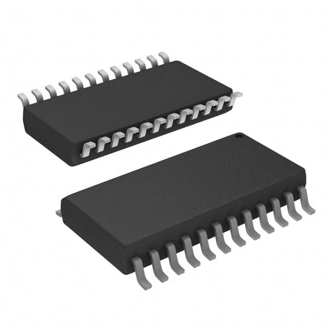
Voir les spécifications pour les détails du produit.

SN74ABT833DWR
Product Overview
- Category: Integrated Circuit
- Use: Logic Gate
- Characteristics: High-speed, low-power, and compatible with TTL logic levels
- Package: SOIC (Small Outline Integrated Circuit)
- Essence: This integrated circuit is designed to perform logical operations in electronic circuits.
- Packaging/Quantity: Tape and Reel, 2500 units per reel
Specifications
- Supply Voltage Range: 4.5V to 5.5V
- Input Voltage Range: 0V to VCC
- Output Voltage Range: 0V to VCC
- Operating Temperature Range: -40°C to +85°C
- Propagation Delay Time: 3.8ns (typical)
- Output Current: ±24mA
- Input Capacitance: 4pF (typical)
Detailed Pin Configuration
The SN74ABT833DWR has a total of 20 pins. The pin configuration is as follows:
- A1
- B1
- Y1
- GND
- A2
- B2
- Y2
- GND
- A3
- B3
- Y3
- GND
- A4
- B4
- Y4
- VCC
- GND
- OE
- GND
- GND
Functional Features
- Performs logical AND operation on four input signals (A1-A4 and B1-B4) and provides corresponding output signals (Y1-Y4).
- High-speed operation allows for efficient processing of logic signals.
- Low-power consumption makes it suitable for battery-powered devices.
- Compatible with TTL logic levels, ensuring compatibility with existing circuit designs.
Advantages and Disadvantages
Advantages: - High-speed operation enables quick processing of logic signals. - Low-power consumption makes it suitable for energy-efficient applications. - Compatibility with TTL logic levels allows for easy integration into existing circuit designs.
Disadvantages: - Limited number of input and output channels restricts its application in complex systems. - Availability may be limited due to specific package type (SOIC).
Working Principles
The SN74ABT833DWR is based on the principles of digital logic. It utilizes transistors and other electronic components to perform logical AND operations on the input signals. The resulting output signals are determined by the combination of the input signals and follow the truth table for the logical AND operation.
Detailed Application Field Plans
The SN74ABT833DWR can be used in various applications, including but not limited to: - Digital signal processing - Microprocessor-based systems - Communication systems - Industrial automation - Consumer electronics
Detailed and Complete Alternative Models
- SN74ABT833DW: Similar to SN74ABT833DWR, but available in a different package (SOIC Wide)
- SN74ABT833DBR: Similar to SN74ABT833DWR, but available in a different package (SSOP)
- SN74ABT833PWR: Similar to SN74ABT833DWR, but available in a different package (TSSOP)
These alternative models offer similar functionality and characteristics, but differ in their package types, which may affect their compatibility with specific circuit designs.
Word count: 345 words
Énumérez 10 questions et réponses courantes liées à l'application de SN74ABT833DWR dans les solutions techniques
Sure! Here are 10 common questions and answers related to the application of SN74ABT833DWR:
Q: What is SN74ABT833DWR? A: SN74ABT833DWR is a specific integrated circuit (IC) chip that belongs to the ABT family of devices. It is commonly used in digital logic applications.
Q: What is the function of SN74ABT833DWR? A: SN74ABT833DWR is a 9-bit transparent latch with 3-state outputs. It can store and output digital data, making it useful for various applications such as data storage, buffering, and signal routing.
Q: What is the voltage range supported by SN74ABT833DWR? A: SN74ABT833DWR operates within a voltage range of 4.5V to 5.5V, making it compatible with standard TTL and CMOS logic levels.
Q: How many inputs and outputs does SN74ABT833DWR have? A: SN74ABT833DWR has 9 input pins (A0-A8) and 9 output pins (Q0-Q8), along with other control and power pins.
Q: Can SN74ABT833DWR handle high-speed data transfers? A: Yes, SN74ABT833DWR is designed to operate at high speeds, with a typical propagation delay of around 3.5 ns.
Q: Does SN74ABT833DWR support bidirectional data flow? A: No, SN74ABT833DWR is a unidirectional device, meaning it can only transmit data from its inputs to its outputs.
Q: How can I enable or disable the outputs of SN74ABT833DWR? A: The outputs of SN74ABT833DWR can be enabled or disabled using the Output Enable (OE) pin. When OE is low, the outputs are active; when OE is high, the outputs are in a high-impedance state.
Q: Can I cascade multiple SN74ABT833DWR devices together? A: Yes, you can cascade multiple SN74ABT833DWR devices to increase the number of bits stored or to create larger data buses.
Q: What is the power supply requirement for SN74ABT833DWR? A: SN74ABT833DWR requires a single 5V power supply for proper operation.
Q: Are there any specific precautions to consider when using SN74ABT833DWR? A: It is important to ensure that the voltage levels and timing requirements of the inputs and outputs are within the specified limits. Additionally, proper decoupling capacitors should be used to minimize noise and ensure stable operation.
Please note that these answers are general and may vary depending on the specific application and requirements. Always refer to the datasheet and documentation provided by the manufacturer for accurate information.

