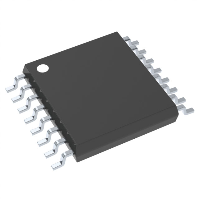
Voir les spécifications pour les détails du produit.

CD4015BPWR
Product Overview
Category
CD4015BPWR belongs to the category of integrated circuits (ICs).
Use
This product is commonly used in digital electronic circuits for various applications.
Characteristics
- CD4015BPWR is a dual 4-bit static shift register.
- It operates on a wide voltage range, typically between 3V and 18V.
- The IC has a high noise immunity and can withstand significant voltage fluctuations.
- It offers a low power consumption, making it suitable for battery-powered devices.
- CD4015BPWR is known for its reliable performance and durability.
Package
The CD4015BPWR is available in a small outline package (SOIC) with a width of 3.9mm.
Essence
The essence of CD4015BPWR lies in its ability to store and shift data bits in digital circuits.
Packaging/Quantity
This product is typically packaged in reels containing 2500 units.
Specifications
- Supply Voltage: 3V - 18V
- Operating Temperature Range: -55°C to +125°C
- Logic Family: CMOS
- Number of Bits: 4
- Package Type: SOIC
- Package Width: 3.9mm
Detailed Pin Configuration
The CD4015BPWR has a total of 16 pins, which are assigned specific functions as follows:
- Pin 1: Serial Data Input (DS)
- Pin 2: Clock Input (CP)
- Pin 3: Parallel Data Output Q1
- Pin 4: Parallel Data Output Q2
- Pin 5: Serial Data Output (Q7S)
- Pin 6: Master Reset (MR)
- Pin 7: Clock Enable (CE)
- Pin 8: Ground (GND)
- Pin 9: Clock Input (CP)
- Pin 10: Serial Data Input (DS)
- Pin 11: Parallel Data Output Q3
- Pin 12: Parallel Data Output Q4
- Pin 13: Serial Data Output (Q7S)
- Pin 14: Master Reset (MR)
- Pin 15: Clock Enable (CE)
- Pin 16: VDD (Supply Voltage)
Functional Features
- CD4015BPWR can store and shift data bits in a serial or parallel manner.
- It has a master reset function to clear the register.
- The clock enable feature allows control over the shifting operation.
- This IC operates on a wide voltage range, making it versatile for various applications.
Advantages and Disadvantages
Advantages
- Wide operating voltage range
- Low power consumption
- High noise immunity
- Reliable performance
- Compact package size
Disadvantages
- Limited number of bits (4 bits)
- Requires external components for complete functionality
Working Principles
The CD4015BPWR is based on CMOS technology and utilizes flip-flops to store and shift data. When the clock input receives a pulse, the data is shifted from one flip-flop to another. The master reset function clears the register, while the clock enable feature controls the shifting operation.
Detailed Application Field Plans
CD4015BPWR finds applications in various digital electronic circuits, including but not limited to: - Shift registers - Data storage systems - Serial-to-parallel converters - LED displays - Communication devices
Detailed and Complete Alternative Models
- CD4015BE: DIP package, 16-pin configuration
- CD4015BM: SOIC package, 16-pin configuration
- CD4015BCN: PDIP package, 16-pin configuration
- CD4015BD: SOIC package, 16-pin configuration
These alternative models offer similar functionality and can be used as substitutes for CD4015BPWR.
Word count: 511 words
Énumérez 10 questions et réponses courantes liées à l'application de CD4015BPWR dans les solutions techniques
Sure! Here are 10 common questions and answers related to the application of CD4015BPWR:
Q: What is CD4015BPWR?
A: CD4015BPWR is a CMOS dual 4-stage static shift register, commonly used in digital logic circuits.Q: What is the maximum operating voltage for CD4015BPWR?
A: The maximum operating voltage for CD4015BPWR is typically 18V.Q: How many flip-flops are there in CD4015BPWR?
A: CD4015BPWR consists of two independent 4-bit shift registers, each containing four flip-flops.Q: What is the clock input frequency range for CD4015BPWR?
A: The clock input frequency range for CD4015BPWR is typically from DC to 10 MHz.Q: Can CD4015BPWR be used as a counter?
A: Yes, CD4015BPWR can be cascaded to form larger counters by connecting the output of one chip to the input of another.Q: What is the power supply voltage range for CD4015BPWR?
A: The power supply voltage range for CD4015BPWR is typically from 3V to 18V.Q: Does CD4015BPWR have any built-in latches?
A: No, CD4015BPWR does not have any built-in latches. It only has flip-flops for storing data.Q: Can CD4015BPWR be used in serial-to-parallel data conversion?
A: Yes, CD4015BPWR can be used to convert serial data into parallel data using its shift register functionality.Q: What is the typical propagation delay of CD4015BPWR?
A: The typical propagation delay of CD4015BPWR is around 60 ns.Q: Can CD4015BPWR be used in both rising and falling edge-triggered applications?
A: Yes, CD4015BPWR can be used in both rising and falling edge-triggered applications by connecting the clock input accordingly.
Please note that the answers provided here are general and may vary depending on specific datasheet specifications and application requirements.

