

Voir les spécifications pour les détails du produit.
STGF5H60DF
Introduction
The STGF5H60DF is a semiconductor device belonging to the category of Insulated Gate Bipolar Transistors (IGBTs). This entry provides an overview of the basic information, specifications, pin configuration, functional features, advantages and disadvantages, working principles, application field plans, and alternative models of the STGF5H60DF.
Basic Information Overview
- Category: Insulated Gate Bipolar Transistor (IGBT)
- Use: Power switching applications in various electronic devices and systems
- Characteristics: High voltage capability, low saturation voltage, fast switching speed
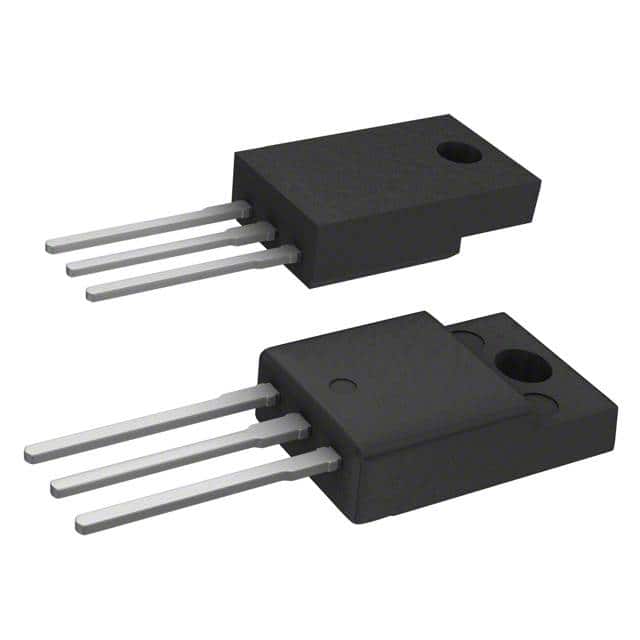
- Package: TO-220FP
- Essence: Efficient power control and management
- Packaging/Quantity: Typically available in reels or tubes containing multiple units
Specifications
- Voltage Rating: 600V
- Current Rating: 10A
- Maximum Operating Temperature: 150°C
- Gate-Emitter Voltage (VGE): ±20V
- Collector-Emitter Saturation Voltage (VCE(sat)): 1.8V
- Turn-off Time (toff): 100ns
Detailed Pin Configuration
The STGF5H60DF IGBT typically consists of three main terminals: 1. Collector (C) 2. Emitter (E) 3. Gate (G)
Functional Features
- High voltage capability enables use in power electronics applications
- Low saturation voltage minimizes power loss during operation
- Fast switching speed allows for efficient power control
Advantages and Disadvantages
Advantages
- High voltage capability suitable for diverse applications
- Low saturation voltage leads to improved energy efficiency
- Fast switching speed enhances overall performance
Disadvantages
- Sensitivity to overvoltage conditions
- Limited current-carrying capacity compared to some alternatives
Working Principles
The STGF5H60DF operates based on the principles of controlling the flow of current between the collector and emitter terminals using the gate signal. When a positive voltage is applied to the gate terminal, it allows the current to flow between the collector and emitter, enabling power switching functionality.
Detailed Application Field Plans
The STGF5H60DF finds extensive use in various applications, including: - Motor drives - Uninterruptible power supplies (UPS) - Renewable energy systems - Induction heating systems - Welding equipment
Detailed and Complete Alternative Models
Some alternative models to the STGF5H60DF include: - STGW30NC60WD - IRG4BC20KD - FGA25N120ANTD
In conclusion, the STGF5H60DF IGBT offers high voltage capability, low saturation voltage, and fast switching speed, making it suitable for a wide range of power switching applications across different industries.
Word count: 366
Énumérez 10 questions et réponses courantes liées à l'application de STGF5H60DF dans les solutions techniques
What is STGF5H60DF?
- STGF5H60DF is a fast-switching, high-voltage, ultrafast diode with soft recovery characteristics, commonly used in power electronic applications.
What are the key features of STGF5H60DF?
- The key features include a high repetitive peak reverse voltage, low forward voltage drop, fast and soft recovery, and high reliability.
In what technical solutions can STGF5H60DF be used?
- STGF5H60DF can be used in various technical solutions such as power supplies, motor drives, inverters, and welding equipment.
What are the benefits of using STGF5H60DF in technical solutions?
- The benefits include improved efficiency, reduced switching losses, enhanced thermal performance, and increased system reliability.
What is the maximum operating temperature for STGF5H60DF?
- The maximum operating temperature for STGF5H60DF is typically around 175°C.
How does STGF5H60DF contribute to energy savings in technical solutions?
- STGF5H60DF's low forward voltage drop and fast recovery help minimize power dissipation and improve overall energy efficiency.
Are there any application notes or reference designs available for using STGF5H60DF?
- Yes, STMicroelectronics provides application notes and reference designs to assist engineers in implementing STGF5H60DF in various technical solutions.
What are the typical input/output characteristics of STGF5H60DF?
- The typical input/output characteristics include forward voltage drop, reverse recovery time, and leakage current at specified operating conditions.
Can STGF5H60DF be used in high-frequency applications?
- Yes, STGF5H60DF is suitable for high-frequency applications due to its fast-switching and soft recovery characteristics.
Where can I find detailed specifications and application guidelines for STGF5H60DF?
- Detailed specifications and application guidelines for STGF5H60DF can be found in the product datasheet and application notes provided by STMicroelectronics.