

Voir les spécifications pour les détails du produit.
DM74S64N
Product Overview
- Category: Integrated Circuit (IC)
- Use: Logic Gate
- Characteristics: Quad 2-Input OR Gate
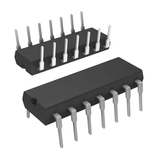
- Package: DIP (Dual In-line Package)
- Essence: The DM74S64N is a logic gate integrated circuit that performs the OR operation on two input signals.
- Packaging/Quantity: The DM74S64N is typically sold in packs of 25 units.
Specifications
- Supply Voltage: 4.75V to 5.25V
- Operating Temperature: -55°C to +125°C
- Propagation Delay: 9ns (typical)
- Output Current: ±8mA
- Input Voltage: 0V to VCC
Detailed Pin Configuration
The DM74S64N has a total of 14 pins, which are assigned specific functions as follows:
- Pin 1: Input A1
- Pin 2: Input B1
- Pin 3: Output Y1
- Pin 4: Ground (GND)
- Pin 5: Input A2
- Pin 6: Input B2
- Pin 7: Output Y2
- Pin 8: VCC (+5V)
- Pin 9: Input A3
- Pin 10: Input B3
- Pin 11: Output Y3
- Pin 12: Input A4
- Pin 13: Input B4
- Pin 14: Output Y4
Functional Features
- The DM74S64N is a quad 2-input OR gate, meaning it can perform the logical OR operation on two input signals.
- It operates with a supply voltage range of 4.75V to 5.25V, making it compatible with standard TTL logic levels.
- The propagation delay of the DM74S64N is typically 9ns, ensuring fast and efficient operation.
- It has a high output current capability of ±8mA, allowing it to drive multiple loads simultaneously.
Advantages and Disadvantages
Advantages
- Compact and space-saving DIP package.
- Wide operating temperature range (-55°C to +125°C).
- Fast propagation delay for quick signal processing.
- High output current capability for driving multiple loads.
Disadvantages
- Limited number of inputs (2 per gate).
- Requires external pull-up or pull-down resistors for proper input signal handling.
- Not suitable for applications requiring complex logical operations.
Working Principles
The DM74S64N operates based on the principles of digital logic. It performs the OR operation on two input signals, producing an output signal that is high (logic 1) if either or both of the inputs are high. If both inputs are low (logic 0), the output signal will also be low.
The internal circuitry of the DM74S64N consists of transistors and resistors arranged in a specific configuration to achieve the desired logical function. When the input signals are applied, the transistors within the IC respond accordingly, resulting in the appropriate output signal.
Detailed Application Field Plans
The DM74S64N can be used in various applications where logical OR operations are required. Some common application fields include:
- Digital electronics: The DM74S64N can be used in digital circuits to combine multiple input signals and generate a single output based on the logical OR operation.
- Arithmetic circuits: It can be utilized in arithmetic circuits to perform addition or subtraction operations by combining multiple input bits.
- Control systems: The DM74S64N can be employed in control systems to implement decision-making logic based on multiple input conditions.
Detailed and Complete Alternative Models
- SN74LS32N: Quad 2-Input OR Gate, DIP package.
- CD4071BE: Quad 2-Input OR Gate, DIP package.
- MC14071BCP: Quad 2-Input OR Gate, DIP package.
- 74HC32N: Quad 2-Input OR Gate, DIP package.
These alternative models offer similar functionality to the DM74S64N and can be used as replacements depending on specific requirements.
In conclusion, the DM74S64N is a quad 2-input OR gate integrated circuit that provides a compact and efficient solution for logical OR operations. With its fast propagation delay and high output current capability, it finds applications in various digital and control systems.
Énumérez 10 questions et réponses courantes liées à l'application de DM74S64N dans les solutions techniques
Sure! Here are 10 common questions and answers related to the application of DM74S64N in technical solutions:
Q: What is DM74S64N? A: DM74S64N is a specific type of integrated circuit (IC) chip, commonly known as a quad 2-input OR gate.
Q: What is the purpose of DM74S64N? A: The purpose of DM74S64N is to perform logical OR operations on two input signals, producing an output signal based on their logical combination.
Q: How many inputs does DM74S64N have? A: DM74S64N has four inputs, allowing you to perform OR operations on up to four different input signals.
Q: What voltage levels does DM74S64N support? A: DM74S64N typically supports standard TTL (Transistor-Transistor Logic) voltage levels, which are 0V for logic low and around 5V for logic high.
Q: Can DM74S64N be used in both digital and analog circuits? A: No, DM74S64N is specifically designed for digital circuits and is not suitable for use in analog applications.
Q: What is the maximum frequency at which DM74S64N can operate? A: The maximum operating frequency of DM74S64N is typically around 25 MHz, but it may vary depending on the specific conditions and setup.
Q: Can DM74S64N be used in high-speed data processing applications? A: While DM74S64N can handle moderate frequencies, it may not be ideal for high-speed data processing due to its limited speed capabilities.
Q: Is DM74S64N compatible with other logic families like CMOS or ECL? A: DM74S64N is not directly compatible with other logic families like CMOS (Complementary Metal-Oxide-Semiconductor) or ECL (Emitter-Coupled Logic). Level-shifting may be required for interfacing.
Q: Can DM74S64N be used in both commercial and industrial applications? A: Yes, DM74S64N can be used in a wide range of applications, including both commercial and industrial settings, as long as the voltage levels and operating conditions are within its specifications.
Q: Are there any specific precautions to consider when using DM74S64N? A: It is important to ensure that the power supply voltages and currents are within the specified limits, and proper decoupling capacitors should be used to minimize noise and voltage spikes. Additionally, static discharge precautions should be taken to avoid damaging the IC during handling.