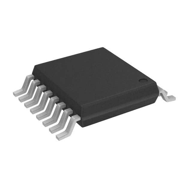
Voir les spécifications pour les détails du produit.

Encyclopedia Entry: 74ACT139MTCX
Product Overview
Category
The 74ACT139MTCX belongs to the category of integrated circuits (ICs) and specifically falls under the family of digital multiplexers/demultiplexers.
Use
This product is primarily used in digital electronics for data routing and selection purposes. It allows multiple input signals to be directed to one of several outputs, or vice versa.
Characteristics
- High-speed operation: The 74ACT139MTCX is designed to operate at high clock frequencies, making it suitable for applications requiring fast data processing.
- Low power consumption: This IC is optimized for low power consumption, ensuring efficient energy usage.
- Wide operating voltage range: It can operate within a wide voltage range, typically between 2V and 6V.
- Compatibility: The 74ACT139MTCX is compatible with both TTL (Transistor-Transistor Logic) and CMOS (Complementary Metal-Oxide-Semiconductor) logic levels.
- Compact package: It is available in a small-sized TSSOP (Thin Shrink Small Outline Package), which facilitates space-saving integration into electronic systems.
Packaging/Quantity
The 74ACT139MTCX is commonly packaged in reels or tubes, containing a quantity of 250 or 300 units per package.
Specifications
- Supply Voltage Range: 2V to 6V
- Input Voltage Range: 0V to VCC
- Output Voltage Range: 0V to VCC
- Operating Temperature Range: -40°C to +85°C
- Propagation Delay Time: 5 ns (typical)
- Maximum Quiescent Current: 4 mA
Detailed Pin Configuration
The 74ACT139MTCX has a total of 16 pins, each serving a specific function:
- A0: Address Input 0
- A1: Address Input 1
- G1: Enable Input 1
- G2: Enable Input 2
- Y0: Output 0
- Y1: Output 1
- Y2: Output 2
- Y3: Output 3
- VCC: Positive Power Supply
- GND: Ground
- Y4: Output 4
- Y5: Output 5
- Y6: Output 6
- Y7: Output 7
- A2: Address Input 2
- NC: No Connection
Functional Features
The 74ACT139MTCX is a dual 2-to-4 line decoder/demultiplexer with active-low outputs. It features two enable inputs (G1 and G2) that control the data routing functionality. When both enable inputs are high, all outputs are in a high-impedance state.
This IC can be used as a demultiplexer by providing the appropriate address inputs (A0, A1, and A2) to select one of the four output lines. Alternatively, it can function as a decoder by using the same address inputs to activate one of the four output lines while keeping the remaining outputs inactive.
Advantages and Disadvantages
Advantages
- High-speed operation allows for efficient data processing.
- Low power consumption ensures energy efficiency.
- Wide operating voltage range provides flexibility in various applications.
- Compatibility with TTL and CMOS logic levels enables easy integration into existing systems.
- Compact package saves space in electronic designs.
Disadvantages
- Limited number of output lines may restrict certain complex applications.
- Active-low outputs may require additional circuitry for specific use cases.
Working Principles
The 74ACT139MTCX operates based on the principles of digital logic. It utilizes address inputs to select one of the output lines, either as a demultiplexer or decoder. The enable inputs control the activation and deactivation of the outputs, allowing for efficient data routing.
Detailed Application Field Plans
The 74ACT139MTCX finds applications in various fields, including but not limited to: - Data communication systems - Multiplexing/demultiplexing circuits - Address decoding in microcontrollers - Memory selection in digital storage devices - Signal routing in audio/video equipment
Detailed and Complete Alternative Models
Some alternative models that offer similar functionality to the 74ACT139MTCX include: - 74HC139: A CMOS version with comparable specifications. - CD74AC139: An alternate IC from a different manufacturer. - SN74LS139: A TTL version with similar features.
These alternatives can be considered based on specific project requirements and availability.
Word count: 550 words
Énumérez 10 questions et réponses courantes liées à l'application de 74ACT139MTCX dans les solutions techniques
Sure! Here are 10 common questions and answers related to the application of 74ACT139MTCX in technical solutions:
Question: What is the function of the 74ACT139MTCX?
Answer: The 74ACT139MTCX is a dual 2-to-4 decoder/demultiplexer IC, which means it can decode two separate binary inputs into four output lines.Question: What is the operating voltage range for the 74ACT139MTCX?
Answer: The 74ACT139MTCX operates within a voltage range of 4.5V to 5.5V.Question: Can the 74ACT139MTCX be used for both decoding and demultiplexing applications?
Answer: Yes, the 74ACT139MTCX can be used for both decoding and demultiplexing purposes, depending on the specific requirements of the circuit.Question: How many input pins does the 74ACT139MTCX have?
Answer: The 74ACT139MTCX has two input pins, A0 and A1, which are used to select the desired output line.Question: What is the maximum frequency at which the 74ACT139MTCX can operate?
Answer: The 74ACT139MTCX can operate at a maximum frequency of 125 MHz.Question: Can the 74ACT139MTCX be cascaded to increase the number of output lines?
Answer: Yes, multiple 74ACT139MTCX ICs can be cascaded together to increase the number of output lines as required.Question: Does the 74ACT139MTCX have any built-in enable pins?
Answer: No, the 74ACT139MTCX does not have any built-in enable pins. The outputs are always active based on the input selection.Question: What is the output logic level of the 74ACT139MTCX?
Answer: The 74ACT139MTCX has TTL-compatible outputs, which means the logic high level is approximately equal to Vcc and the logic low level is close to 0V.Question: Can the 74ACT139MTCX be used in both commercial and industrial applications?
Answer: Yes, the 74ACT139MTCX is suitable for use in both commercial and industrial applications due to its wide operating temperature range.Question: Are there any specific precautions to consider when using the 74ACT139MTCX?
Answer: It is important to ensure that the power supply voltage does not exceed the specified range, and proper decoupling capacitors should be used to minimize noise and voltage spikes. Additionally, care should be taken to avoid exceeding the maximum input current ratings.

