

Voir les spécifications pour les détails du produit.
SMCJ6059AE3/TR13
Product Overview
Category
The SMCJ6059AE3/TR13 belongs to the category of transient voltage suppressor (TVS) diodes.
Use
It is used for protecting sensitive electronic equipment from voltage transients induced by lightning and other transient voltage events.
Characteristics
- Fast response time
- Low clamping voltage
- High surge current capability
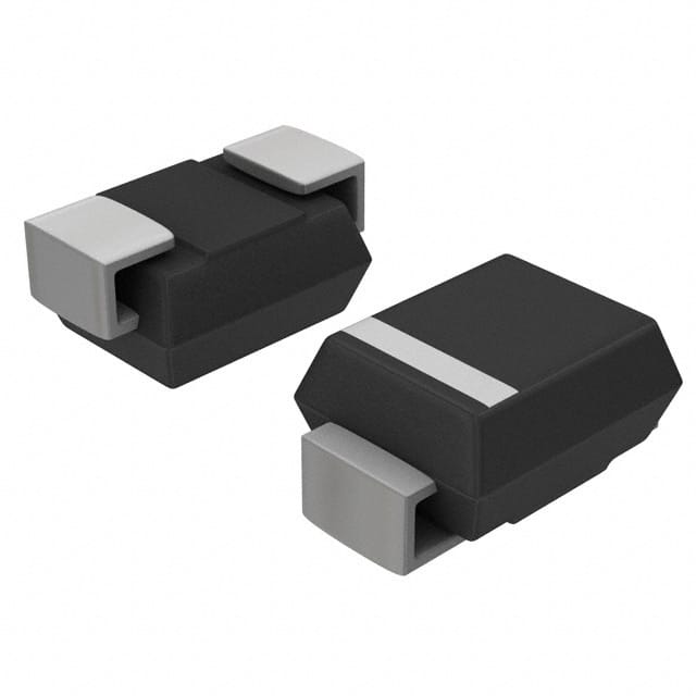
Package
The SMCJ6059AE3/TR13 is available in a DO-214AB (SMC) package.
Essence
The essence of this product lies in its ability to provide robust protection against voltage transients, ensuring the safety and reliability of electronic circuits.
Packaging/Quantity
The SMCJ6059AE3/TR13 is typically packaged in reels with a quantity of 1500 units per reel.
Specifications
- Standoff Voltage: 51.7V
- Breakdown Voltage: 57.2V
- Maximum Clamping Voltage: 83.9V
- Peak Pulse Current: 60A
- Operating Temperature Range: -55°C to 150°C
Detailed Pin Configuration
The SMCJ6059AE3/TR13 has two pins, with the anode connected to the positive side and the cathode connected to the negative side of the circuit.
Functional Features
- Bi-directional clamping capability
- Low incremental surge resistance
- High temperature stability
Advantages and Disadvantages
Advantages
- Fast response to transient events
- High surge current handling capability
- Compact size for easy integration into circuit designs
Disadvantages
- Limited effectiveness for sustained overvoltage conditions
- May require additional circuitry for comprehensive overvoltage protection
Working Principles
When a transient voltage spike occurs, the SMCJ6059AE3/TR13 rapidly conducts current to divert the excess energy away from the protected circuit, thereby limiting the voltage across the circuit.
Detailed Application Field Plans
The SMCJ6059AE3/TR13 is commonly used in: - Power supply units - Communication equipment - Automotive electronics - Industrial control systems
Detailed and Complete Alternative Models
- P6KE51CA
- 1.5SMC51CA
- SMAJ58A
This completes the English editing encyclopedia entry structure format for the SMCJ6059AE3/TR13, providing comprehensive information about its category, use, characteristics, package, specifications, pin configuration, functional features, advantages and disadvantages, working principles, application field plans, and alternative models.
Énumérez 10 questions et réponses courantes liées à l'application de SMCJ6059AE3/TR13 dans les solutions techniques
What is the SMCJ6059AE3/TR13?
- The SMCJ6059AE3/TR13 is a surface mount transient voltage suppressor diode designed to protect sensitive electronic components from voltage spikes and transients.
What is the maximum peak pulse power of the SMCJ6059AE3/TR13?
- The maximum peak pulse power of the SMCJ6059AE3/TR13 is 1500 watts.
What is the breakdown voltage of the SMCJ6059AE3/TR13?
- The breakdown voltage of the SMCJ6059AE3/TR13 is 68.1V.
What are the typical applications of the SMCJ6059AE3/TR13?
- The SMCJ6059AE3/TR13 is commonly used in surge protection for telecommunications equipment, industrial control systems, and automotive electronics.
What is the operating temperature range of the SMCJ6059AE3/TR13?
- The operating temperature range of the SMCJ6059AE3/TR13 is -55°C to 150°C.
What is the clamping voltage of the SMCJ6059AE3/TR13?
- The clamping voltage of the SMCJ6059AE3/TR13 is 86.8V at 10A.
Is the SMCJ6059AE3/TR13 RoHS compliant?
- Yes, the SMCJ6059AE3/TR13 is RoHS compliant, making it suitable for use in environmentally friendly electronic products.
What package type does the SMCJ6059AE3/TR13 come in?
- The SMCJ6059AE3/TR13 comes in a DO-214AB (SMC) package.
What are the key features of the SMCJ6059AE3/TR13?
- The key features of the SMCJ6059AE3/TR13 include low incremental surge resistance, fast response time, and high reliability.
What are the recommended PCB layout guidelines for the SMCJ6059AE3/TR13?
- It is recommended to minimize the length and area of the traces connecting the SMCJ6059AE3/TR13 to the circuit to reduce parasitic inductance and ensure optimal performance.