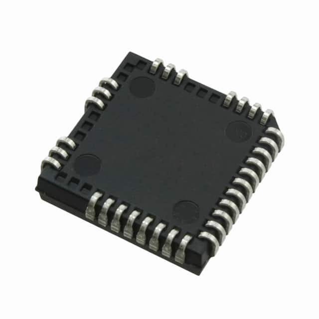
Voir les spécifications pour les détails du produit.

IRS2332JPBF
Overview
Category: Integrated Circuit (IC)
Use: Motor Drive and Control
Characteristics: - High voltage, high speed power MOSFET and IGBT driver - Designed for three-phase motor control applications - Provides protection features such as under-voltage lockout (UVLO) and over-current protection (OCP) - Suitable for use in industrial automation, robotics, and electric vehicle applications
Package: Power DIP-16
Essence: The IRS2332JPBF is a high-performance IC designed to drive power MOSFETs and IGBTs in three-phase motor control applications. It offers advanced protection features and is widely used in various industries.
Packaging/Quantity: The IRS2332JPBF is typically sold in reels or tubes containing 50 units per package.
Specifications
- Supply Voltage Range: 10V - 20V
- Output Current: 1.5A (peak)
- Operating Temperature Range: -40°C to +125°C
- Maximum PWM Frequency: 500kHz
- UVLO Threshold: 9.5V (typical)
- OCP Threshold: 0.5V (typical)
Pin Configuration
The IRS2332JPBF IC has a total of 16 pins arranged as follows:
___________
      |           |
   1  |  2  3  4  |  5
   6  |  7  8  9  | 10
  11  | 12 13 14  | 15
      |___________|
Pin Description: 1. VCC: Positive supply voltage 2. HO1: High-side gate driver output 1 3. LO1: Low-side gate driver output 1 4. HO2: High-side gate driver output 2 5. LO2: Low-side gate driver output 2 6. VSS: Ground 7. VS: Bootstrap supply voltage 8. HB1: High-side bootstrap input 1 9. LB1: Low-side bootstrap input 1 10. HB2: High-side bootstrap input 2 11. LB2: Low-side bootstrap input 2 12. SD: Shutdown input 13. VREF: Reference voltage for UVLO and OCP 14. RT: External resistor connected to set dead time 15. CT: External capacitor connected to set dead time 16. NC: No connection
Functional Features
- High-speed gate drive capability
- Integrated bootstrap diodes for high-side gate drivers
- Protection against under-voltage and over-current conditions
- Adjustable dead time for optimized switching performance
- Logic-level inputs compatible with microcontrollers and digital signal processors (DSPs)
Advantages and Disadvantages
Advantages: - High-performance motor control solution - Comprehensive protection features enhance system reliability - Compact package size for space-constrained applications - Wide operating temperature range allows for versatile usage
Disadvantages: - Requires external components for proper operation - Limited maximum PWM frequency compared to some other ICs in the market
Working Principles
The IRS2332JPBF is designed to drive power MOSFETs and IGBTs in three-phase motor control applications. It utilizes high-speed gate drivers to provide efficient switching of these devices. The integrated bootstrap diodes simplify the design by eliminating the need for external diodes in the high-side gate drive circuitry. The IC also incorporates protection features such as under-voltage lockout (UVLO) and over-current protection (OCP) to safeguard the motor and the driver circuitry.
Detailed Application Field Plans
The IRS2332JPBF is widely used in various applications, including:
- Industrial Automation: Used in motor control systems for conveyor belts, pumps, fans, and other industrial machinery.
- Robotics: Enables precise control of motors in robotic arms, automated vehicles, and other robotic systems.
- Electric Vehicles: Facilitates efficient motor control in electric cars, scooters, and bikes.
Detailed and Complete Alternative Models
Some alternative models to the IRS2332JPBF that offer similar functionality are:
- IR2104: Dual high- and low-side driver IC with similar features and package options.
- TC4420/TC4429: High-speed MOSFET drivers suitable for motor control applications.
- HIP4081A: Three-phase bridge driver IC with integrated bootstrap diodes and protection features.
These alternative models can be considered based on specific application requirements and availability.
Word count: 570 words
Énumérez 10 questions et réponses courantes liées à l'application de IRS2332JPBF dans les solutions techniques
Sure! Here are 10 common questions and answers related to the application of IRS2332JPBF in technical solutions:
Q: What is IRS2332JPBF? A: IRS2332JPBF is a high-performance, dual-channel low-side driver IC designed for use in various applications such as motor control, power supplies, and inverters.
Q: What is the maximum voltage rating of IRS2332JPBF? A: The maximum voltage rating of IRS2332JPBF is typically around 600V.
Q: Can IRS2332JPBF be used for driving MOSFETs or IGBTs? A: Yes, IRS2332JPBF is specifically designed to drive both MOSFETs and IGBTs.
Q: What is the maximum current that IRS2332JPBF can handle? A: IRS2332JPBF can handle a maximum peak output current of up to 2A per channel.
Q: Does IRS2332JPBF have built-in protection features? A: Yes, IRS2332JPBF includes various protection features like under-voltage lockout (UVLO), over-current protection (OCP), and thermal shutdown.
Q: What is the operating temperature range of IRS2332JPBF? A: IRS2332JPBF has an operating temperature range of -40°C to +125°C.
Q: Can IRS2332JPBF be used in automotive applications? A: Yes, IRS2332JPBF is suitable for automotive applications as it meets the necessary standards and requirements.
Q: What is the typical switching frequency supported by IRS2332JPBF? A: IRS2332JPBF supports a typical switching frequency range of 0Hz to 500kHz.
Q: Does IRS2332JPBF require an external bootstrap diode? A: No, IRS2332JPBF has an integrated high-voltage level-shift circuitry that eliminates the need for an external bootstrap diode.
Q: Can IRS2332JPBF be used in both low-side and high-side configurations? A: No, IRS2332JPBF is specifically designed for low-side configurations only. For high-side applications, a complementary driver IC is required.
Please note that these answers are general and may vary depending on the specific application and requirements. It's always recommended to refer to the datasheet and consult with technical experts for accurate information.

